Rear Panel Description
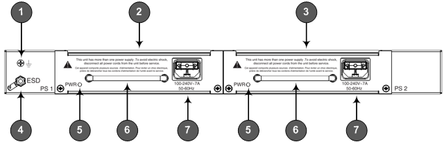
The chassis rear panel with AC and DC power configurations are displayed in the figures below and described in the subsequent table.
Rear-Panel AC Power Configuration
Rear-Panel DC Power Configuration
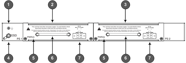
Rear-Panel Description
|
Item # |
Label |
Description |
||||||
|---|---|---|---|---|---|---|---|---|
|
1 |
|
Protective earthing (grounding) screw. |
||||||
|
2 |
PS 1 |
Power Supply module No. 1. For more information, see Power Supply Modules . |
||||||
|
3 |
PS 2 |
Power Supply module No. 2. For more information, see Power Supply Modules . |
||||||
|
4 |
ESD |
Electrostatic Discharge (ESD) lug. |
||||||
|
5 |
PWR |
Power status LED for indicating the status of the Power Supply module. For more information, see Power Supply Modules . |
||||||
|
6 |
- |
Extraction-handle for removing the Power Supply module. |
||||||
|
7 |
AC: 100-240V~7A DC: DC IN 48V 17A MAX |
|
